 tincanmakingmachine.net
Weld Seam Liquid Coating: Equipment, Processes, and Troubleshooting
(1) Roller Coating Equipment: Inner coating device for weld seams, with a coating box mounted on a coating arm connected to the welding arm. When the tank body is transported to the coating wheel after welding, the coating of the weld seam is performed. This method involves applying liquid coating to the weld seam on the tank body using a roller, driven by a motor. The coating amount on the roller is controlled by a scraper. The coating wheel surface is processed into different curves to control the thickness of the liquid coating. The coating wheel system is placed in a coating box, and the coating material is supplied to the coating box from a coating tank through pneumatic pressure. The coating box also has a coating liquid level detection device to control the amount of coating material supplied from the coating tank to the coating box. The coating wheel’s coating surface is designed with different curves, including convex curves, straight lines, and concave curves, to control the thickness of the coating. The coating box is mounted on a support, and the coating liquid control is simple, maintaining a constant coating liquid level using the principle of pressure balance inside and outside the coating bottle.
Most external weld seam coatings use roller coating devices, which work in conjunction with the oxygen-free protection process to enhance the aesthetic appearance and rust prevention of the tank body weld seam.
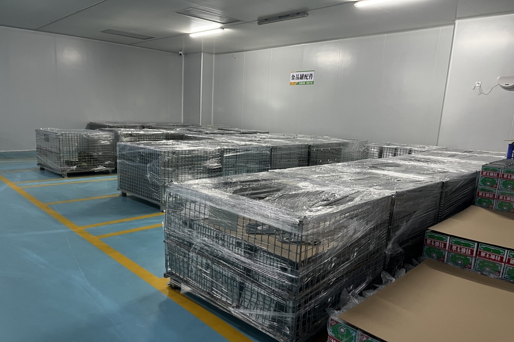
For external weld seam coating devices, refer to Figure 3-71, including the coating box, tank conveyor belt, and control system. Liquid coating accessories are shown in Figure 3-72.
(2) Spray Equipment: No-air spray system, commonly used for internal weld seam liquid coating equipment by most manufacturers. Generally, it is an improved system based on the one invented by the American company NORDSON. The main components include an air pressure coating pump (air pressure-to-hydraulic ratio of 1:16), filter, coating heater, coating hydraulic pressure regulating valve, spray gun, nozzle, and a circulation valve group forming a closed-loop circuit. An electrical control system controls the coating heater temperature and the spray switch time of the nozzle. This coating process involves atomizing the liquid coating through a special nozzle, spraying it onto the weld seam. Good coating results are achieved by adjusting nozzle hole size, coating viscosity, coating temperature, spray pressure, and diluents. There are air and non-air atomization nozzles. The principles of non-air spray are shown in Figure 3-73.
Coating viscosity should be determined based on data provided by the coating manufacturer or experimental results. DIN4 viscosity cup (volume 100 mL, hole diameter 4 mm, ambient temperature 20°C) is commonly used for viscosity measurement. The coating pump sucks the coating into the pipeline (see Figure 3-76), and the pressure can be increased to 2-4 MPa. The main components of the spray system are as follows:
1. Liquid Coating Boost Pump: Driven by compressed air, the piston cylinder moves up and down, pressurizing the liquid coating to the required pressure (usually 2-4 MPa) in a ratio of 16:1. The pressure is determined based on the coating width, selected nozzle, coating viscosity, and coating temperature.
2. Coating Heater (see Figure 3-77): Reduces the viscosity of the liquid coating to increase the solid content after spraying, enhances the evaporation rate of the solvent, reduces the surface tension of the coating, and improves the adhesion of the coating layer. The liquid coating pipeline system usually has a circulation valve.
Notably, in non-air spray nozzles (see Figure 3-81), when working, they are mounted on the spray gun. The head is made of hard alloy material, and the special-shaped small holes are processed by a special method, allowing the liquid coating to form a fan-shaped atomization under high pressure. These nozzles come in various styles and different aperture sizes to adapt to different coatings. There are three types of hole shapes:
1. Standard Type (S-standard): The nozzle has “cat-eye-shaped” small holes, producing a fan-shaped atomization, suitable for certain liquid coatings.
2. Cross-Cut Type (X-cross-cuts): The nozzle has a square hole, providing clear fan-shaped atomization and higher adaptability to various coatings, resulting in a more even distribution of the coating. The cross-cut type may perform better than the standard type for some coatings but similar for others.
3. Flow Coating Type (F-FLOW-COATING): This nozzle offers the best coating effect, with minimal overspray and excellent coverage. It is suitable for both traditional and some special liquid coatings. After prolonged use, nozzles may wear differently, affecting their performance.
When selecting the nozzle model, it is essential to conduct tests based on different liquid coatings or follow the recommendations from the liquid coating supplier.
Additionally, when changing coatings, it is crucial to clean the pipeline, use appropriate diluents, and avoid mixing different liquid coatings, which may result in adverse effects on the adjustment, debugging, and final coating results.
(3) Baking and Curing Process of Liquid Coatings: After applying liquid coatings to the weld seam area, a curing process is required to polymerize the coatings. The protective effect of the coatings applied to the weld seam also depends on the baking and curing temperature and time, especially for applications like high-temperature sterilization at 121-129°C for 90 minutes in the food industry.
The curing device consists of an oven and a conveyor belt. The conveyor belt transports the coated tank body through the oven at a specific speed and holds it for a certain period. The hot air in the oven cures the coatings, forming a chemically stable coating layer. The ends of the oven can extract volatile solvents, as shown in Figure 3-82. The baking and curing process of liquid coating generally consists of two stages:
1. Solvent Evaporation Stage: This is a physical reaction. During the initial stage of baking in the oven, the solvent in the wet coating layer needs to evaporate fully before the solid components of the coating cure. Otherwise, if the coating surface begins to cure while the solvent has not completely evaporated, continued solvent evaporation can create bubbles on the surface of the cured coating, damaging the protective layer.
2. Coating Curing Stage: This is a chemical reaction. After the solvent in the coating layer applied to the tank body weld seam has completely evaporated, the solid content undergoes a polymerization reaction at the high temperature of the oven for 10-20 seconds (different coatings have different properties). This process transforms low-molecular-weight compounds into high-molecular-weight compounds, giving the coating layer the characteristics of high-molecular-weight compounds and achieving rust resistance and corrosion resistance. The distribution of coating thickness after baking and curing is shown in Figure 3-83.
Experience shows that approximately 1 second of baking time is required for every 1 μm of cured liquid coating layer. By using an improved solvent formula that ensures the required solder melting temperature for the coating and without bubbles, it is possible to reduce baking time by 30%.
The curing curve of liquid coating is shown in Figures 3-84 and 3-85, with the initial stage being the solvent evaporation period at lower temperatures and the later stage being the curing period at higher temperatures.
During the baking process, temperature and time are crucial parameters. Higher baking temperatures may lead to the following results:
– Good curing of the coating
layer.
– The coating layer may become too thin.
– The external ink layer may change color, and the tank may be scratched during transportation.
– Shorter baking time for curing.
The impact of baking and curing time is as follows:
– Less prone to bubbling during baking and curing, resulting in a well-cured coating layer.
– Favorable for subsequent processes, such as high-temperature sterilization.
– Adequate coating film thickness. Lower baking temperatures are beneficial for the equipment’s lifespan.
The distribution of the coating belt during baking, the actual state of the liquid coating layer, and the ideal state may differ significantly, especially in thinner areas of the weld seam (see Figure 3-86).
(4) Common Issues in the Baking and Curing Process of Liquid Coating Belts:
1. Coating Belt Deviation: Poor adjustment of the tank conveyor belt or poor connection between two conveyor belts can cause the tank body to rotate on the conveyor belt, misaligning the nozzle or internal roller coating wheel with the weld seam, resulting in coating belt deviation (see Figure 3-87). This affects the protective effect of the coating layer. The solution is to patiently adjust the conveyor belt to ensure smooth movement of the tank body on the conveyor belt without rotation.
2. Anomalies in Four Scenarios:
a. Coating Layer Too Thin After Curing: Possible causes include low solid content in the liquid coating, requiring an increase in solid content or coating viscosity. For roller coating, choose a roller with a thick coating curve. For spraying, increase the coating pump pressure and coating heater temperature, or switch to a larger nozzle. Alternatively, slow down the conveyor belt speed.
b. Coating Layer Porous After Curing (Microbubbles): This may result from too fast curing, causing the coating to boil and form bubbles and blister-like micropores. The solution is to slow down the curing speed by reducing the conveyor belt speed or lowering the temperature of the heating oven in the early stage.
c. Coating Layer with Bubbles: Bubbles may form in the coating layer during solvent evaporation or spraying. If the curing speed is too fast and the surface coating begins to cure while the solvent continues to evaporate, or if bubbles from the coating are not eliminated during spraying, bubbles and small pores may be left on the surface of the cured coating. Using the wrong solvent, such as toluene or banana water commonly used for regular paints, can also lead to bubbles that are difficult to eliminate during the curing of the liquid coating belt, as shown in Figure 3-89. Sometimes, bubbles form on the weld seam, as shown in Figure 3-90. The cause may be excessive heat on the weld seam and slightly higher viscosity of the coating. The solution is to add a cooling device after welding or reduce the viscosity slightly.
d. Poor Coverage of the Mouth Iron Edge Weld Seam Area: The quality of welding has a significant impact on the protective coating layer. Reasons and solutions for this issue include: i. Weld seam splatter: Slightly increase the overlap amount of the weld seam during welding or reduce the welding current to smooth the weld seam, facilitating coating repair. ii. Insufficient coating viscosity: Increase coating viscosity and correspondingly increase coating temperature.
3. Overspray: Some coating material outside the welding seam repair belt causes an impact on aesthetics (see Figures 3-91 and 3-92). Sometimes, these coatings are difficult to cure. Causes and solutions include: i. Coating viscosity is too low, requiring an increase in viscosity. ii. Incorrect nozzle type, meaning the selected nozzle has a width that is too narrow, causing the nozzle-to-weld seam distance to be too far, resulting in atomized coating drifting to other parts of the tank body. The solution is to choose the correct nozzle type.
4. Splattering: The repair belt is too fine, accompanied by splattering at both ends (see Figure 3-93). Causes and solutions include: i. Low spray pressure or pipeline blockage, requiring an increase in pressure. Check the pipeline. ii. Coating viscosity is too high, requiring a reduction in viscosity and an increase in the coating heater temperature. iii. The nozzle is too close to the tank body, requiring adjustment.
 tincanmakingmachine.net