Tinplate Printing Inspection and CTP Technology Overview

The specific inspection criteria and methods refer to QB1877-1993 Packaging and Decoration of Tinplate (Chromium-Plated) Printed Products.
Main New Technology: CTP Technology

1. Definition
Computer To Plate (CTP, offline direct plate making)
Computer To Press (on-press direct plate making)
Computer To Paper/Print (direct printing)
Computer To Proof (direct digital color proofing)
Computer-to-Conventional Plate (direct conventional PS plate making)
Currently, unless otherwise specified, CTP generally refers to Computer To Plate, which is an offline direct plate-making system. This system bypasses intermediate processes such as film making or plate exposure. The prepress system’s edited and imposition-ready layout is directly imaged on the printing plate using laser scanning to form the plate.

2. Development History
1960s–1970s: Theoretical research phase
1970s–1980s: Lacked theoretical support, remained in experimental and exploratory stage
1990s: Technology matured and achieved industrial application
1995 DRUPA Exhibition: The official “birth year” of CTP technology
1995–1997: Many large printing companies adopted CTP systems, but costs were high
1997–1998: Prices dropped significantly; small and medium printing plants began adoption
1998–present: Widely applied abroad; in domestic tinplate printing, adoption is still effectively “0”

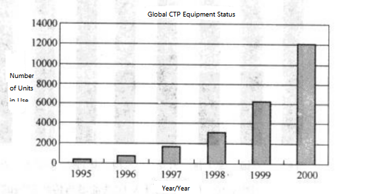
Figure 3-23 Current Global Application of CTP Equipment

Figure 3-23 Current Global Application of CTP Equipment

(3) Current Global Application of CTP Equipment
The current global application of CTP equipment is shown in Figure 3-23.
(4) Plate-Making Process
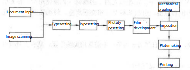
① Laser Imaging Process: The laser imaging process is shown in Figure 3-24.

Figure 3-24 Laser Imaging Process Flow

Figure 3-24 Laser Imaging Process Flow

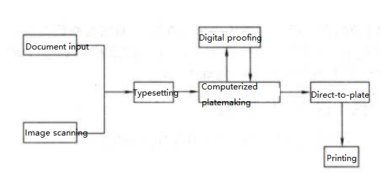
②Figure 3-25 CTP Direct Plate-Making Process
As can be seen, the CTP process is much simpler compared with traditional laser imaging.
Advantages of CTP Technology:
CTP technology enables the transition from semi-digital and semi-analog prepress processes to fully digital prepress.

Figure 3-25CTP direct plate making process

Figure 3-25CTP direct plate making process

② It improves work efficiency, simplifies processes, and shortens plate-making time, as well as prepress preparation time.

③ It enhances print quality, as fewer steps make quality control easier.

④ CTP technology ensures reliable use of frequency-modulated (FM) screening.

Limitations of CTP Technology: High cost.

High-Fidelity Printing Technology:

Compared with traditional printing, patterns are clearer, colors are more vivid, and the color gamut is wider. Currently, Hangzhou COFCO Packaging possesses this technology.。

Advanced Printing Equipment Features

1. High Speed:Currently capable of reaching 10,000 sheets/hour with continuous feeding.
2. Automation ①Automatic ink volume adjustment
②Automatic ink path cleaning
③Automatic cleaning of blanket, plate, and impression roller
④Automatic mounting and changing of printing plates
⑤Automatic registration system
⑥Dual feeding and dual delivery for continuous material supply
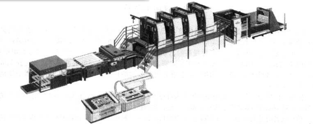
3. Multi-color Printing:Figure 3-27 shows a B+K four-color UV printing machine.

Figure 3-27 B+K four-color UV printing machine

Figure 3-27 B+K four-color UV printing machine

(4) Intelligent ① Color scanning control system; ② PS plate image scanning system.
(5) Quality stability control ① Ink roller cooling system; ② Stable ink supply system.
(6) UV curing equipment ELC@= lamp power electronic control
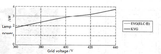
①The impact of grid voltage fluctuations on lamp power. As shown in Figure 3-28

Figure 3-28 EVG (ELC@) lamp power change diagram

Figure 3-28 EVG (ELC@) lamp power change diagram

Notes on Transformers in Printing Equipment
1. KVG (Conventional Transformer)
At low voltage: Lamp power decreases; effective efficiency η = 85%–92%
At high voltage: Lamp power increases, may overload; effective efficiency η = 85%–92%
2. EVG (ELC® Electronic Control Transformer)
Maintains stable lamp power even with fluctuations in mains voltage; effective efficiency η = 95%–97%
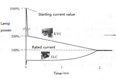
3. Full-load Startup Current
As shown in Figure 3-29
ELC® eliminates startup peaks, provides higher power conversion efficiency, and ensures smooth load distribution
Conclusion
Modern printing equipment emphasizes durability, high performance, high speed, and low energy loss. With the rapid development of the packaging industry, the prospects for both printing equipment and the printing sector are very promising.

Figure 3-29 EVG (ELC®) full-load starting current variation diagram

Figure 3-29 EVG (ELC®) full-load starting current variation diagram

Key Welding Machine Operation Points

In actual welding machine operation, different machines may vary slightly, but the basic principles are the same. Therefore, every part of the welding machine must be adjusted according to the operation manual, with particular attention to the following key points:

  1. Plate specifications, dimensions, squareness, and burrs must meet requirements, and the magazine should be properly adjusted.
  2. Sucker, pusher, double sheet detector, flexer, pre-roll forming, and roll forming must be correctly adjusted.
  3. The working height of the Z-bar and the lower welding wheel should be adjusted according to the lower wheel correction.
  4. The roller guider and calibration crown should be properly adjusted for tightness, vertical, and horizontal position. The can body opening shape must meet requirements, and the overlap deviation at both ends should be less than 0.10 mm.
  5. Synchronization and over-push settings must be correct.
  6. The copper wire forming dimensions must meet requirements, the process should run smoothly, and the tin marks on the upper and lower wheels should be centered with a gap of about 1.5 mm. That is, the lower wheel is centered on the Z-bar, and the upper wheel is centered on the lower wheel, ensuring the weld nugget is centered.
    After passing through the welding station, the copper wire elongation should be less than 2–3%, and the touch temperature should be normal.
  7. Welding pressure should be adjusted according to material thickness and quality. After setting, adjust the welding current to the upper limit where weld spatter (irregular welds) occurs, then to the lower limit where the weld mechanically opens or tears (delamination). Finally, adjust the welding current to achieve the optimal weld quality, usually about the upper one-third between the limits.

Weld Seam Coating and Curing

Overview

Since 1978, with the development of Super-WIMA resistance welding in the canning industry, the overlap of can body weld seams has been reduced to 0.4–0.6 mm. Lead-free tin-plated resistance-welded cans have been widely used for food and beverage cans. This transition has significantly improved the overall quality of can body weld overlaps. To achieve flawless weld seams, applying a protective coating layer that does not damage the contents is an essential process. The protection and anti-corrosion of can body weld seams have thus been widely adopted, ensuring safer and more reliable use of resistance-welded cans. This process requires weld seam coating equipment and curing/oven equipment, as shown in Figure 3-50.

Figure 3-50 Schematic of the Relationship Between Welding Machine and Coating Curing Device

PCE-120, CPF, PRCTD, LARC, CHS represent coating curing devices.

PCE-120 – Powder box

CPF – Small powder box

PRC – External coating

LARC – Conveyor

GHS – Gas oven

PNEUM, EJECTOR – Ejection device

However, depending on different conditions, regions, can contents, and storage duration, the protection and corrosion-resistance quality parameters for can body welds vary. Therefore, addressing weld corrosion is a major challenge, as corrosion can occur in different forms. Additionally, sterilization processes for canned food and carbonation in beverages like beer and soft drinks introduce technical issues for the weld seam coating process.

The weld seam protection and corrosion-resistance process mainly consists of two stages: the coating process and the curing process for the coating layer.

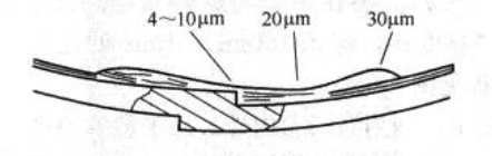
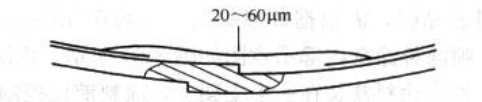
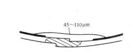
In the coating process, coatings are categorized into liquid coating coating and powder coating coating, each with different coating thicknesses and protective effects, as shown in Figures 3-51, 3-52, and 3-53.

Figure 3-51 Coating Layer of Liquid Coating
Layer is thin, especially in the weld seam area

Figure 3-51 Coating Layer of Liquid Coating

Layer is thin, especially in the weld seam area

Figure 3-52 Coating Layer of Thermosetting Powder Coating, Layer is Relatively Thick

Figure 3-52 Coating Layer of Thermosetting Powder Coating, Layer is Relatively Thick

Figure 3-53 Coating Layer of Thermoplastic Powder Coating, Thickest Layer

Figure 3-53 Coating Layer of Thermoplastic Powder Coating, Thickest Layer

Multicolor UV Curing Printing Technology: Development, Principles, and Advantages

(1) Development History
1970 – Introduced
Early 1980s – 10% UV ink / no UV varnish
Early 1990s – Slow development of UV inks; interest in UV varnish increased
1996 – Rapid development of UV inks and varnishes
2000 – UV inks and varnishes widely used in metal printing
2004 – Began to replace traditional printing methods
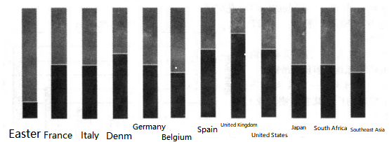
(2) The proportion of UV tinplate inks versus traditional inks worldwide (2005 statistics) is shown in Figure 3-26.

Figure 3-26 Ratio of UV iron printing ink to traditional ink around the world (2005 statistics)

Figure 3-26 Ratio of UV iron printing ink to traditional ink around the world (2005 statistics)

■UV■Traditional

It can be seen that UV tinplate printing technology is already very widespread abroad.

(3) Curing principle Unlike traditional oven drying, UV curing mainly relies on UV curing equipment. Under ultraviolet light (UV) with a wavelength of approximately 180–420 nm, the base materials (photocurable resins) in the ink and varnish undergo polymerization and cross-linking reactions in the presence of a photoinitiator. This reaction rapidly opens the unsaturated double bonds in a very short time, curing the ink and varnish into macromolecules.

(4) Advantages of UV printing technology
① Environmental protection: No volatile organic compounds (VOC) are emitted, so it does not pollute the environment; heating for drying is unnecessary, reducing large amounts of exhaust.
② Energy saving: Without the need for oven drying, gas costs are reduced.
③ Space and maintenance savings: No ovens are required, saving about 50% of the printing floor space and reducing daily maintenance, repairs, and cleaning costs, thereby improving production efficiency.
④ High speed: Instant drying allows for multi-color printing.
⑤ Improved product quality: Reduces scratches caused by holding frames.

(5) Applicable product types
UV inks can generally be used for beverage cans, aerosol cans, food cans, crown caps, and similar products. However, UV varnish currently has some restrictions on beverage and food cans. For two-piece cans with very deep drawing, UV inks and varnish still need further solutions to prevent peeling.

(6) Physical and chemical properties of products
For beverage cans, aerosol cans, food cans, crown caps, and similar products, the color, adhesion, scratch resistance, hardness, and other properties of UV inks and varnish are generally comparable to traditional inks and varnishes.

(7) Current domestic situation
Currently, companies such as COFCO Packaging and Shanghai Baocai have this technology in China

Resistance Welding of Can Bodies

Resistance Welding Equipment and Technology for Can Body Production

Since the late 1980s, China’s can-making industry has made rapid progress in the production technology and processes of three-piece food cans. The key milestone was the abandonment and elimination of soldered can production technology, which had been used for nearly a century, and the introduction of advanced foreign resistance welding machines and modern can-making processes. This brought about a revolutionary transformation in the entire metal packaging industry.

Basic Principle of Resistance Welding

When a small conductor carries a large current, the material resistance of the conductor generates heat. The principle of all resistance welding methods is based on the thermal effect of electric current. A resistance welding machine utilizes the heat generated by the resistance in the welding circuit as the current flows through it, while applying pressure to permanently fuse the metals together, thus achieving welding.
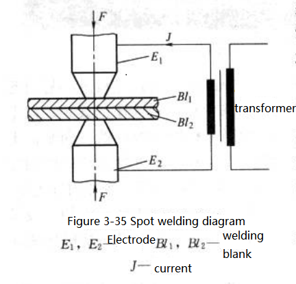
Basic Principle of Resistance Welding

(1) Spot Welding

The principle of spot welding is shown in Fig. 3-35, where Bl1 and Bl2 are welded together.

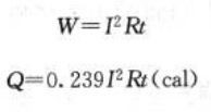
The current required to heat the weld nugget between electrodes E1 and E2 flows through them under a certain pressure. According to Joule’s law, the heat generated between the electrodes is determined by the power W.
Spot Welding

W – Power
Q – Heat
I – Effective current
R – Resistance
t – Time
(1 J = 0.239 cal, i.e., 1 cal = 4.185 J)

When welding current, time, and electrode pressure are properly coordinated, sufficient heat is generated in the weld material, with most of the heat concentrated in the weld nugget. Some heat is lost through water-cooled electrodes, through adjacent workpieces, or radiated into the surrounding air during longer welding times.The total resistance in welding consists of the material resistance and the contact resistance (see Fig. 3-36).

When two conductors are pressed together, current passes through the contact points, which are known as contact resistance or transfer resistance. Since the contact surfaces are not perfectly smooth, small high points first touch and deform under pressure and heat until the entire contact area fuses into one (see Fig. 3-37)
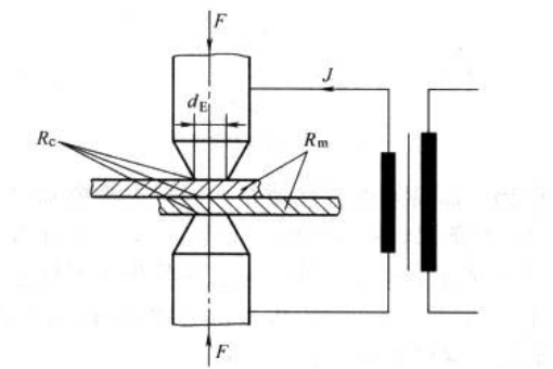
Fig. 3-36 Schematic Diagram of Spot Welding Resistance

Fig. 3-36 Schematic Diagram of Spot Welding Resistance

Rc – Contact resistance
Rm – Metal resistance
dE – Diameter of electrode tip
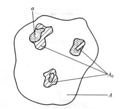
Fig. 3-37 Schematic Diagram of Conductive Contact Surface A – Relative contact surface

Ao – Actual contact surface
a – Single conductive area carrying current
Ea – Actual conductive contact surface, which is smaller than the so-called relative contact surface A, since a perfectly smooth surface is almost impossible. The single conductive area is referred to as (a), and all local conductive areas together are referred to as A.

As electrode pressure increases, the actual contact surface also increases, while the contact resistance decreases. Only when each local contact area (A) is equal can their contact points be equal, but such uniform contact surfaces are rare. For individual contact points, the heat generated by the welding current is not the same, which causes some points to soften or melt. In this way, there is no longer resistance between the electrodes.

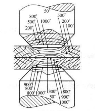
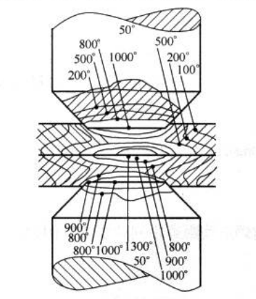
The plastic deformation of the contact points and the formation of new ones increase the total contact area. This process continues until the actual contact surface Ao equals the relative contact surface A. Contact resistance exists only for a limited time during welding. Its effective duration starts when the current is applied and ends when the materials are welded together, as the thin surface layer melts and full contact is achieved. Fig. 3-38 shows the heat distribution during the spot welding process.
Seam Welding with Rolls
Seam welding is essentially continuous spot welding, with spot welding electrodes replaced by rotating welding rolls. Depending on the distance between weld nuggets, the seam can be intermittent (large spacing) or continuous overlapping welds
Figs. 3-39 and 3-40).
Figs. 3-39 and 3-40).

Fig. 3-38 Heat Distribution in Welded Metal and Electrodes
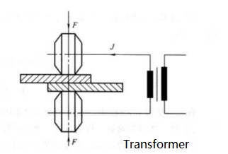
Fig. 3-38 Heat Distribution in Welded Metal and Electrodes

Fig. 3-39 Schematic Diagram of Roller Seam Welding

Fig. 3-39 Schematic Diagram of Roller Seam Welding

Unlike electrodes, welding rolls both transmit the workpiece and carry current and pressure (see Fig. 3-41).
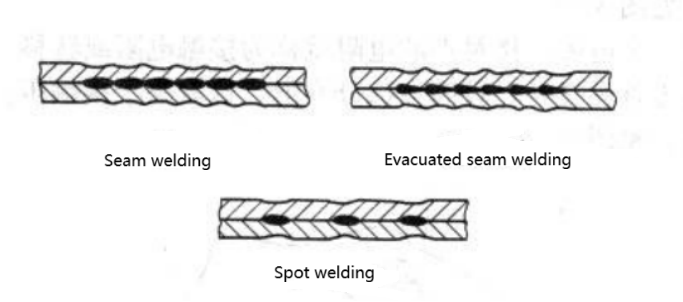
Fig. 3-40 Shapes of Various Weld Seams
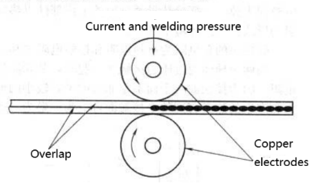
Fig. 3-40 Shapes of Various Weld Seams

Fig. 3-41 Schematic Diagram of Roller Welding

Fig. 3-41 Schematic Diagram of Roller Welding

To ensure good welding quality of tinplate can bodies, the electrodes (welding rolls) must remain clean. To achieve this, grooved welding rolls with a flat copper wire are used. This design ensures that any tin debris is collected by the copper wire instead of adhering to the rolls, maintaining clean electrical contact surfaces at all times (see Fig. 3-42).
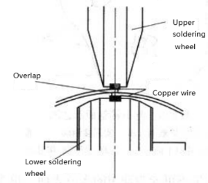
Fig. 3-42 Schematic Diagram of Resistance Welding for Can Making

Fig. 3-42 Schematic Diagram of Resistance Welding for Can Making

Reliable welding contact can only be ensured by strictly following copper wire pressing specifications.

(3) Relationship Between Input Voltage, Frequency, and Welding Current

In seam welding, each half-wave of voltage applied to the rolls produces one weld nugget. Therefore, the welding speed of the rolls is limited by the frequency of the power supply (see Fig. 3-43).
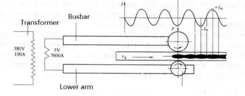
Fig. 3-43 Schematic Diagram of Welding Principle

Fig. 3-43 Schematic Diagram of Welding Principle

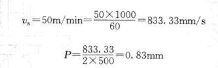
The weld nugget pitch is calculated as: Welding Speed / (2 × Welding Frequency)
Example: For a welding machine with v = 50 m/min and f = 500 Hz, the nugget pitch is:
1

In typical production processes, metal containers have different requirements for weld nugget spacing depending on their specific applications.

Example:
①For pressurized spray cans: typically 0.8–1.0 mm
②For beverage and food cans: typically 1.0–1.2 mm
③For low air-tightness containers (e.g., dry powder or tea cans): 1.2 mm or more
④Heat Distribution in Weld Nuggets
The heat distribution during nugget formation can be divided into zones (see Fig. 3-45):
Zone I: radiation from previous welds and the rising part of the current waveform
Zone II: peak current stage forming the weld nugget
Zone III: radiation from adjacent zones and the falling part of the waveform
Zone II provides most of the welding energy, while the energy of Zones I and III is determined by the nugget pitch.
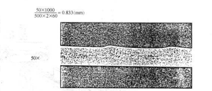
Fig. 3-44 Microsection of Weld Seam
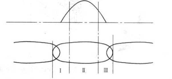
Fig. 3-44 Microsection of Weld Seam

Fig. 3-45 Schematic Diagram of Weld Nugget

Fig. 3-45 Schematic Diagram of Weld Nugget