
 jjyixin
Resistance Welding of Can Bodies
Resistance Welding Equipment and Technology for Can Body Production
Since the late 1980s, China’s can-making industry has made rapid progress in the production technology and processes of three-piece food cans. The key milestone was the abandonment and elimination of soldered can production technology, which had been used for nearly a century, and the introduction of advanced foreign resistance welding machines and modern can-making processes. This brought about a revolutionary transformation in the entire metal packaging industry.
Basic Principle of Resistance Welding
When a small conductor carries a large current, the material resistance of the conductor generates heat. The principle of all resistance welding methods is based on the thermal effect of electric current. A resistance welding machine utilizes the heat generated by the resistance in the welding circuit as the current flows through it, while applying pressure to permanently fuse the metals together, thus achieving welding.
(1) Spot Welding
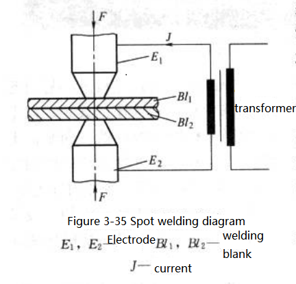
The principle of spot welding is shown in Fig. 3-35, where Bl1 and Bl2 are welded together.
The current required to heat the weld nugget between electrodes E1 and E2 flows through them under a certain pressure. According to Joule’s law, the heat generated between the electrodes is determined by the power W.
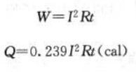
W – Power
Q – Heat
I – Effective current
R – Resistance
t – Time
(1 J = 0.239 cal, i.e., 1 cal = 4.185 J)
When welding current, time, and electrode pressure are properly coordinated, sufficient heat is generated in the weld material, with most of the heat concentrated in the weld nugget. Some heat is lost through water-cooled electrodes, through adjacent workpieces, or radiated into the surrounding air during longer welding times.The total resistance in welding consists of the material resistance and the contact resistance (see Fig. 3-36).
When two conductors are pressed together, current passes through the contact points, which are known as contact resistance or transfer resistance. Since the contact surfaces are not perfectly smooth, small high points first touch and deform under pressure and heat until the entire contact area fuses into one (see Fig. 3-37)
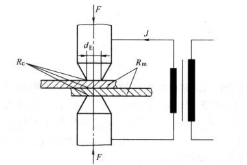
Fig. 3-36 Schematic Diagram of Spot Welding Resistance
Rc – Contact resistance
Rm – Metal resistance
dE – Diameter of electrode tip
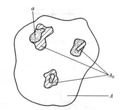
Fig. 3-37 Schematic Diagram of Conductive Contact Surface A – Relative contact surface
Ao – Actual contact surface
a – Single conductive area carrying current
Ea – Actual conductive contact surface, which is smaller than the so-called relative contact surface A, since a perfectly smooth surface is almost impossible. The single conductive area is referred to as (a), and all local conductive areas together are referred to as A.
As electrode pressure increases, the actual contact surface also increases, while the contact resistance decreases. Only when each local contact area (A) is equal can their contact points be equal, but such uniform contact surfaces are rare. For individual contact points, the heat generated by the welding current is not the same, which causes some points to soften or melt. In this way, there is no longer resistance between the electrodes.
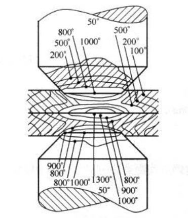
The plastic deformation of the contact points and the formation of new ones increase the total contact area. This process continues until the actual contact surface Ao equals the relative contact surface A. Contact resistance exists only for a limited time during welding. Its effective duration starts when the current is applied and ends when the materials are welded together, as the thin surface layer melts and full contact is achieved. Fig. 3-38 shows the heat distribution during the spot welding process.
Seam Welding with Rolls
Seam welding is essentially continuous spot welding, with spot welding electrodes replaced by rotating welding rolls. Depending on the distance between weld nuggets, the seam can be intermittent (large spacing) or continuous overlapping welds
Figs. 3-39 and 3-40).
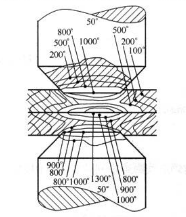
Fig. 3-38 Heat Distribution in Welded Metal and Electrodes
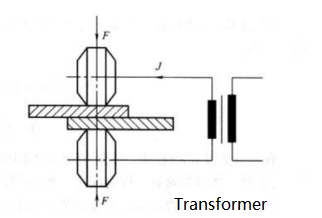
Fig. 3-39 Schematic Diagram of Roller Seam Welding
Unlike electrodes, welding rolls both transmit the workpiece and carry current and pressure (see Fig. 3-41).
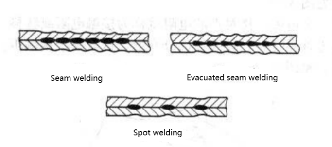
Fig. 3-40 Shapes of Various Weld Seams
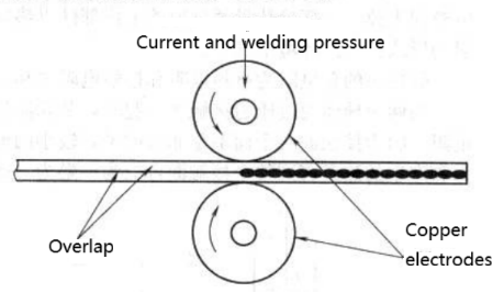
Fig. 3-41 Schematic Diagram of Roller Welding
To ensure good welding quality of tinplate can bodies, the electrodes (welding rolls) must remain clean. To achieve this, grooved welding rolls with a flat copper wire are used. This design ensures that any tin debris is collected by the copper wire instead of adhering to the rolls, maintaining clean electrical contact surfaces at all times (see Fig. 3-42).
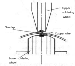
Fig. 3-42 Schematic Diagram of Resistance Welding for Can Making
Reliable welding contact can only be ensured by strictly following copper wire pressing specifications.
(3) Relationship Between Input Voltage, Frequency, and Welding Current
In seam welding, each half-wave of voltage applied to the rolls produces one weld nugget. Therefore, the welding speed of the rolls is limited by the frequency of the power supply (see Fig. 3-43).
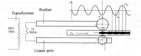
Fig. 3-43 Schematic Diagram of Welding Principle
The weld nugget pitch is calculated as: Welding Speed / (2 × Welding Frequency)
Example: For a welding machine with v = 50 m/min and f = 500 Hz, the nugget pitch is:
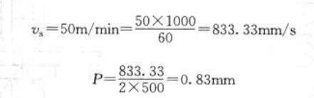
In typical production processes, metal containers have different requirements for weld nugget spacing depending on their specific applications.
Example:
①For pressurized spray cans: typically 0.8–1.0 mm
②For beverage and food cans: typically 1.0–1.2 mm
③For low air-tightness containers (e.g., dry powder or tea cans): 1.2 mm or more
④Heat Distribution in Weld Nuggets
The heat distribution during nugget formation can be divided into zones (see Fig. 3-45):
Zone I: radiation from previous welds and the rising part of the current waveform
Zone II: peak current stage forming the weld nugget
Zone III: radiation from adjacent zones and the falling part of the waveform
Zone II provides most of the welding energy, while the energy of Zones I and III is determined by the nugget pitch.
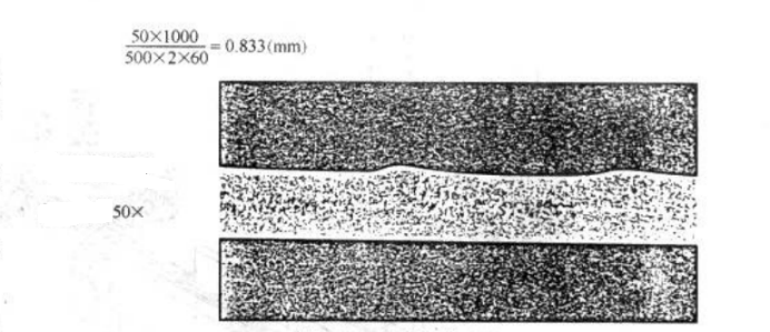
Fig. 3-44 Microsection of Weld Seam
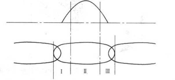
Fig. 3-45 Schematic Diagram of Weld Nugget

 jjyixin